Extrinsic Calibration#
After the intrinsic calibration is done you can move on to the extrinsic calibration. For this you first need to prepare the coordinate points measured during the experiments and possibly prepare the corresponding images.
Image & Point File Preparation#
If you decided on a 3D calibration where you place e.g. a pole on each point on the ground, you need to create one image where all the points are visible at once. For this, it is helpful to combine cutouts of the processed points inside one image (Figure 1). To create such an image, a free programme as e.g. Gimp can be helpful.
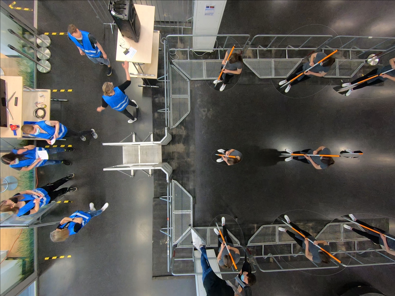
Figure 1: Combined image of all calibration points being processed during the experiments.#
Once the combined image has been created you have to write down the coordinates for each point assigned during the experiment. You can take the coordinates from the sketch that you created during the preparation of the extrinsic calibration on scene.
These coordinates need to be collected in a text editor and saved as a .3dc file. It does not matter where the point
(0,0) is, however, the relations of the point to one another should be represented correctly.
The first line of the file contains the total number of coordinates points in the file. Starting from the second row,
all coordinates should be listed in centimeter according to their X, Y and Z coordinates. You can view an example of
our coordinate system and the corresponding points in Figure 2.
Note
The markings in the picture are solely for your orientation - you do not have to recreate this!
Since we have chosen to mark a coordinate system on the floor and create a 3D system by holding pole of known length
(200 centimeters) on each point, our Z coordinates are either 0 (floor) or 200 (top of pole).
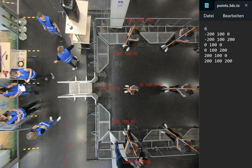
Figure 2: Example of a possible coordinate system and the corresponding point file.#
After you have created your point file save it with the file ending .3dc. This is the file format that can be loaded
into PeTrack.
PeTrack Workflow#
With the combined image of all coordinate points and the point file created, you can now perform the extrinsic calibration in PeTrack. For that, open the image of all combined coordinate points (Figure 1) in PeTrack or drag and drop it into the tab view or video view.
Tip
To avoid shifting the coordinate system while clicking and dragging the mouse in the video tab it is
recommended to check the fix checkbox in the coordinate system and in the alignment grid section
at the bottom of the calibration tab.
Now all coordinate points that are listed in the points file need to be selected in the combined image.
You need to select the points in the same order as they appear in the points file!
You can select the points with Ctrl + double click left mouse button. Select the points as accurate as possible
by zooming into the image. If two of your calibration points are close to one another in the image, Ctrl + double click left mouse button might move one of the points instead of adding a new one. In this case, you can create the new calibration point further away and move it to the desired place using Alt + holding left mouse button.
In case you are unhappy with the selected point you can unselect it by
Ctrl + double click right mouse button.
Tip
If the green circles that appear around the chosen points are too large for your taste, go to the tracking tab in the
tab view and scroll to the path section on the page. Here you can uncheck the head size checkbox
to the right of show current point and now you are able to enter a smaller value of your own choosing. This value
represents the size of the green circles.
Once you have selected all points in the same order as your points file, your chosen points should look similar to the example in Figure 3.

Figure 3: Example of a selected points on the combined image in PeTrack.#
Now you can click on load in the extrinsic parameters section of the calibration tab. Navigate to your points.3dc
file and select it. Now click on fetch and PeTrack will assign the pixel coordinates of your selected points on the
screen to the real-world coordinates written down in the points.3dc file.
You will also note that once you click on fetch your selected points on the screen will disappear.
Then, click on calc to perform the extrinsic calibration, which involves calculating the extrinsic parameters and saving them afterward.
Now you have the option to view the error of your extrinsic calibration by clicking error. This will give you an idea
of e.g. how well you prepared your coordinate system and the accuracy of your point selection in PeTrack. If you are happy
with the results you can click save and the pixel coordinates that were matched to the real-world coordinates will also
be saved in the points.3dc file.
In case you are unhappy with the outcome, you can redo the calibration by selecting new points and loading in the
original points.3dc file again.
Tip
You can view the selected and calculated calibration points by checking the calibration points checkbox in the coordinate system
section. If you notice a point that is particularly bad in alignment with the calibrated value, you can redo the calibration and exclude
this point. This will minimize your error for the extrinsic calibration.
To check the resulting origin of the coordinate system (0,0,0) you can show the coordinate system found in the calibration tab.
After you are finished with the calibration steps it is recommended that you save the PeTrack project with the current calibration status (intrinsic & extrinsic calibration). In case something goes wrong during the following steps, you have a project you can return to and do not have to redo everything from the start.
After this step, you can directly define the walkable area and obstacle polygons in the calibrated view. See Walk Area and Obstacles for the complete workflow.
Tip
To avoid scrolling through the numbers in the calibration tab you can check the immutable checkbox on the top right
of all the sections on the page. This can save you a lot of trouble going forward!