
Performing the Intrinsic and Extrinsic Calibration#
Before starting the experiments, the camera(s) need to be calibrated. At first the intrinsic calibration has to be performed, which corrects for the lens distortion of the camera. This calibration can only be performed once the camera settings are finalized and will not be changed afterwards. Second, the extrinsic calibration is performed, which creates known points in 3D space. This calibration can only be performed once the cameras are safely mounted and will not be moved again.
Intrinsic Calibration#
Preparation#
To perform the intrinsic calibration you first need to prepare your cameras and gather your tools. Only when your camera settings for your experiment have been finalized you can perform the intrinsic calibration.
Regarding tools, we recommend to use
a chessboard pattern
for the calibration, print it and fixate it on e.g. such
a sturdy surface.
Note
The pattern should be completely flat and without wrinkles for the calibration so printing it on a piece of paper will not be sufficient!
Performance#
When performing the calibration it is good to know that only the area starting from the second row to the outer edge of the chessboard is being used for the calculation (Figure 1).
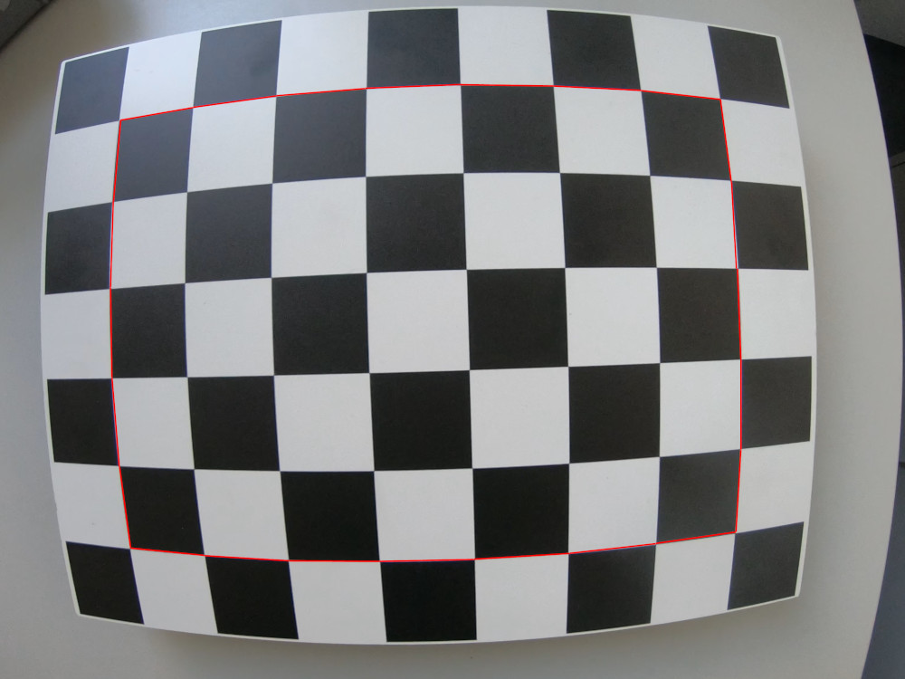
Figure 1: Only the area inside the red rectangle will later be used for the calculation of the intrinsic calibration.#
Now record a short video of the chessboard pattern while trying to bring the area later used for calculation (Figure 1) as close as possible to the edges of your camera view. Move the camera slowly over the chessboard and cover one side after another until the pattern has in total covered the entire view (Figure 2).
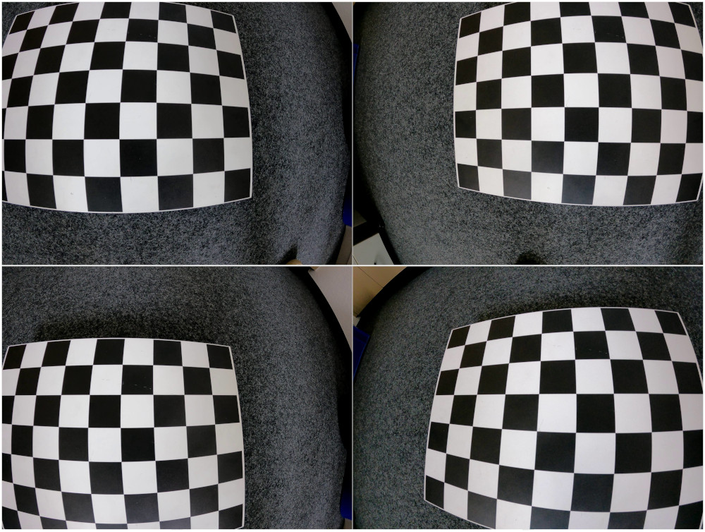
Figure 2: Screenshots from a calibration video focusing of specific areas of the camera view. In total the cover the entire view.#
The reason to cover the entire camera view is that the calibration will only be applied to the covered area. If only the center is covered, the center will be well calibrated but the border region will not! Additionally, try to select an equal number of images covering each side of the camera view, so the calibration will be applied to the entire view equally. You can find examples of calibration images covering the entire view, only the center and heavily the right side of the view in Figure 3.
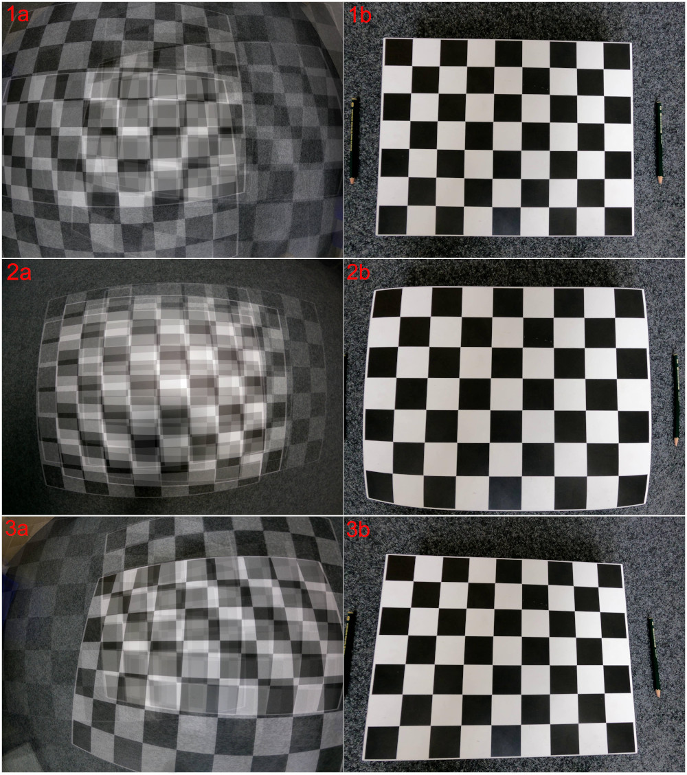
Figure 3: 1a: Overlay of calibration images covering entire view, 1b: Good overall calibration result; 2a: Overlay of calibration images covering only the center, 2b: Good calibration result in the center, poor result around the border; 3a: Overlay of calibration images covering heavily the right side, 3b: Good calibration result on the right side, poor quality on the left side of the image.#
Tip
Since it is best to take the calibration video on scene at the experiments, take your time while recording the video. Move extra slow and even move the area of the chessboard used for calibration out of the camera view. When taking images out of the video you will be able to select the perfect moment in time when the pattern is closest to the border.
Extrinsic Calibration#
Preparation#
In addition to the intrinsic calibration, an extrinsic calibration must also be performed on scene. For this we recommend using a sturdy pole e.g. a ranging pole with a level attached to it (Figure 4). Additionally, a cross laser, measuring rods and adhesive points can be of great help.
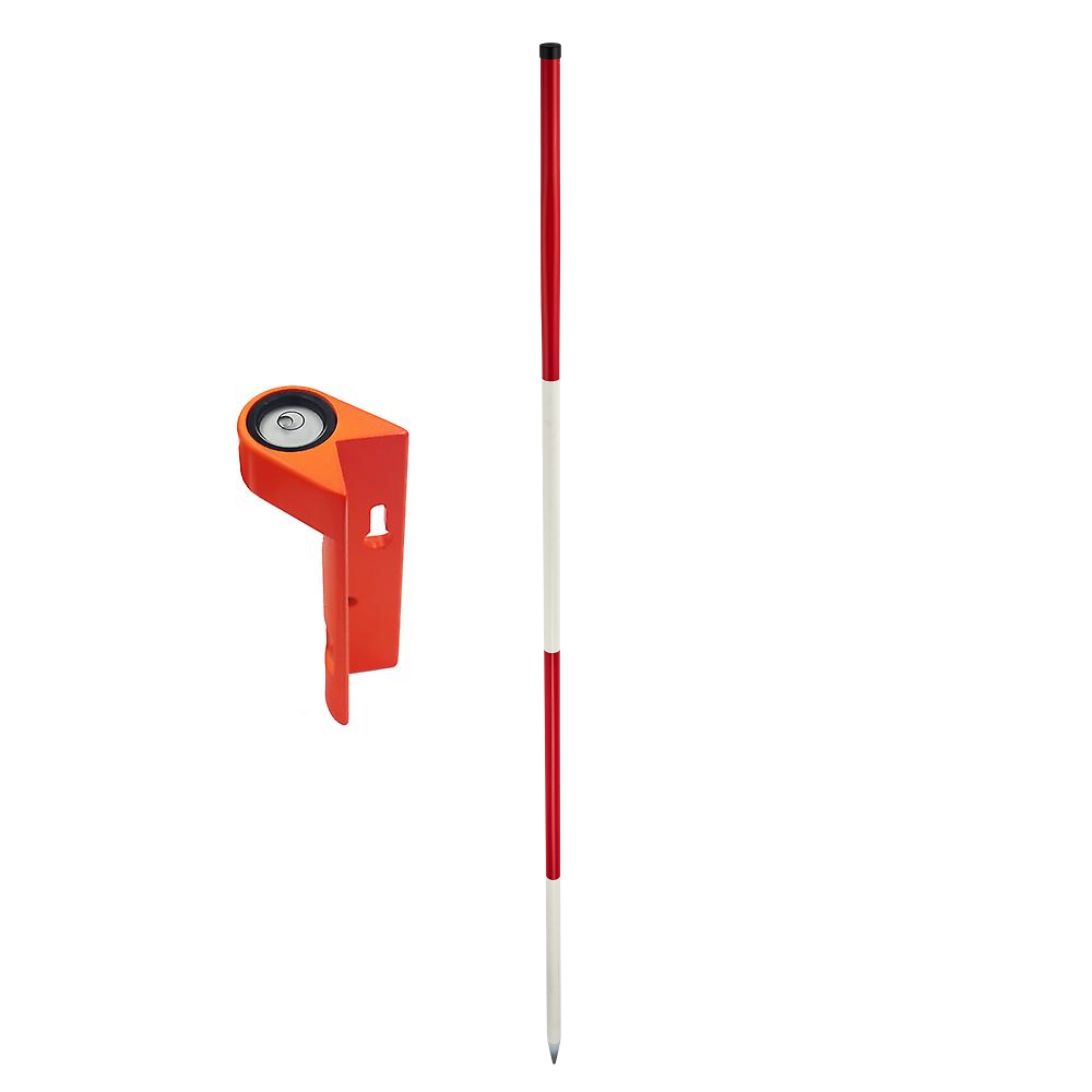
Figure 4: Example of a ranging pole and a level that can be attached to the pole.#
Tip
The pole should be about 2 meters tall to still be close to the head height of pedestrians while at the same time ensuring that the person performing the calibration does not accidentally cover the top of the pole.
Before performing the calibration you should decide on a calibration grid that will be used for the calibration. This grid should be spread over the experimental area and should be prepared by e.g. putting adhesive points on known points on the ground. Hereby it is important to place the points very accurately because even small deviation can cause a big error over the large distance of the experimental area. You can view an example of a 2 meter by 2 meter coordinate grid in Figure 5.
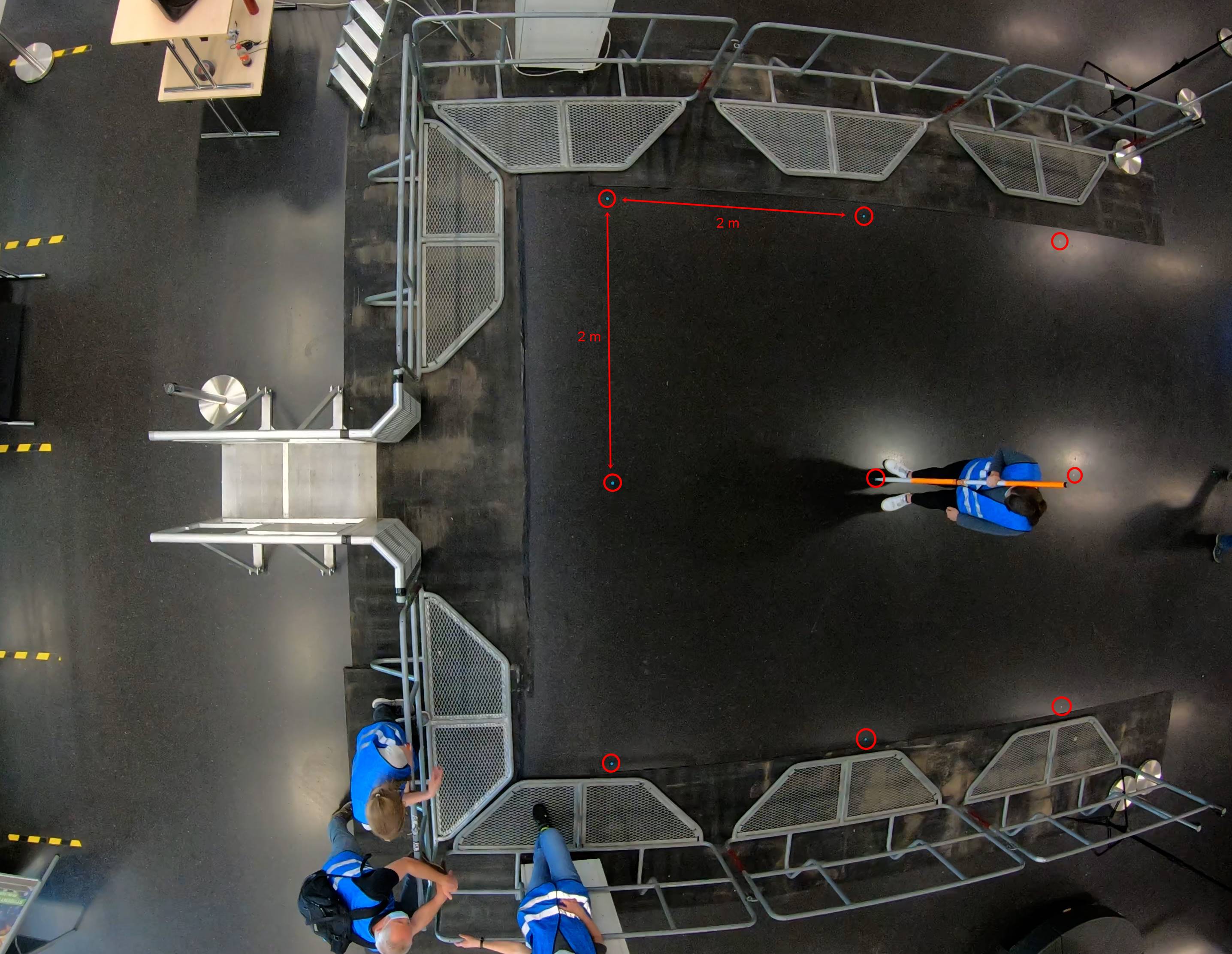
Figure 5: Example of a 2m x 2m coordinate grid. Each put coordinate point is encircled in red.#
Note
Your coordinate grid should have a size that fits the experimental setup. A second option is to measure out objects that are in your experimental area and use them as your coordinate points. However, sometimes it gets tricky to have them cover the entire experimental area and not only the edges.
Create a sketch of your coordinate grid including measurements. You will need this once you perform the extrinsic calibration in PeTrack. Also note down the time at which you are starting the extrinsic calibration. This will help you to locate the calibration, especially in longer video recordings.
Performance#
The aim of the coordinate grid is to log known 3D points in the experimental
setup. There are already known 2D points through the adhesive points on the
ground and by placing the ranging pole (of known height) on the points, we can
add points from the third dimension.
Use the level that is attached to the pole to check the alignment. When you are
happy with the alignment, make e.g. a rapid movement with the pole. Later when
taking images from the video, you can identify the point in time when the pole
was perfectly aligned by navigating to the last frame before the rapid movement
with the pole.
Walk through your coordinate grid and log each calibration point to perform the
extrinsic calibration.
Tip
While performing the calibration, make sure to not stand in between the pole and the camera. This will help you to avoid blocking the view to the point on the ground with your feet or the top of the pole with your head.
After the extrinsic calibration has been recorded, the experiments can be performed.